Marine Guides in English Boat Maintenance
The Physics of Anchoring: Why Chain Weight, Scope and Shock Load Decide Whether Your Anchor Holds
Nafpaktos Marine Boatyard
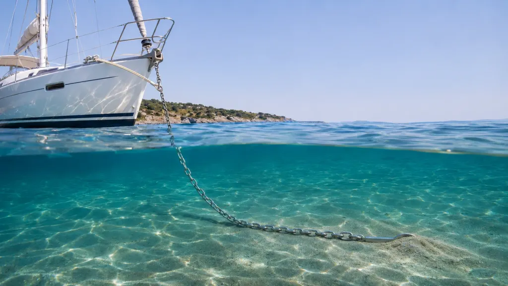
Watch the chain on a calm morning. It disappears into the water at a steep angle, yet it may be pulling almost horizontally at the anchor. Then a squall arrives. The bow falls away, the chain rises, and the same boat, with the same anchor and the same amount of chain out, has a different anchoring system. How much force does it take to make that happen? You can get surprisingly close with a tape measure, a chain data sheet and a calculator.
In 60 seconds
- An anchor resists a horizontal pull. Every degree of upward pull at the shank costs holding power.
- Chain lying on the seabed keeps that pull flat. Its weight is a shock absorber you can calculate.
- Wind load grows with the square of wind speed: 40 knots is four times 20 knots.
- 8 mm over 6 mm buys about twice the breaking load and three-quarters more pull before the chain lifts.
- The same grounded chain can sweep 200 m² of seabed in one wind shift. Drop on sand, not seagrass.
1. The real job of an anchor is to resist a horizontal pull
Imagine pulling a garden spade through sand with its blade buried. Pull along the surface and the blade has to push a wedge of sand out of its way. Pull upwards and you give it a route out. A drag-embedment anchor uses its fluke to engage the seabed in much the same way. Its mass helps it land and begin to set. Once buried, the fluke shape, the soil and the direction of pull govern how much it can resist. Source: Practical Sailor’s discussion of anchor geometry and seabeds.
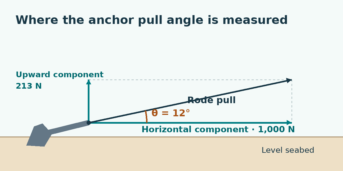
Every pull on the shank can be split into a horizontal part and an upward part. If you already know the horizontal load, the tangent of the pull angle tells you how much upward load accompanies it. Here θ is the angle of the rode where it meets the shank, measured above a level seabed.
Upward force = horizontal force × tan(θ)
With a horizontal pull of 1,000 N and a shank pull angle of 12°, the upward component is 1,000 N × tan(12°) ≈ 213 N. At 0° it is zero. That upward component helps explain why the anchor can lose much more holding capacity than the small change in horizontal force alone would suggest. The soil and anchor move together, and a steepening pull can make the anchor rotate or start to break out.
2. The catenary and the chain on the seabed
Hang a chain between two points and it takes a shape called a catenary. Each link supports the weight of the links below it on the way to the low point. Near that point, the tension is nearly horizontal. Higher up, the tension has a bigger vertical component because it also supports more chain.
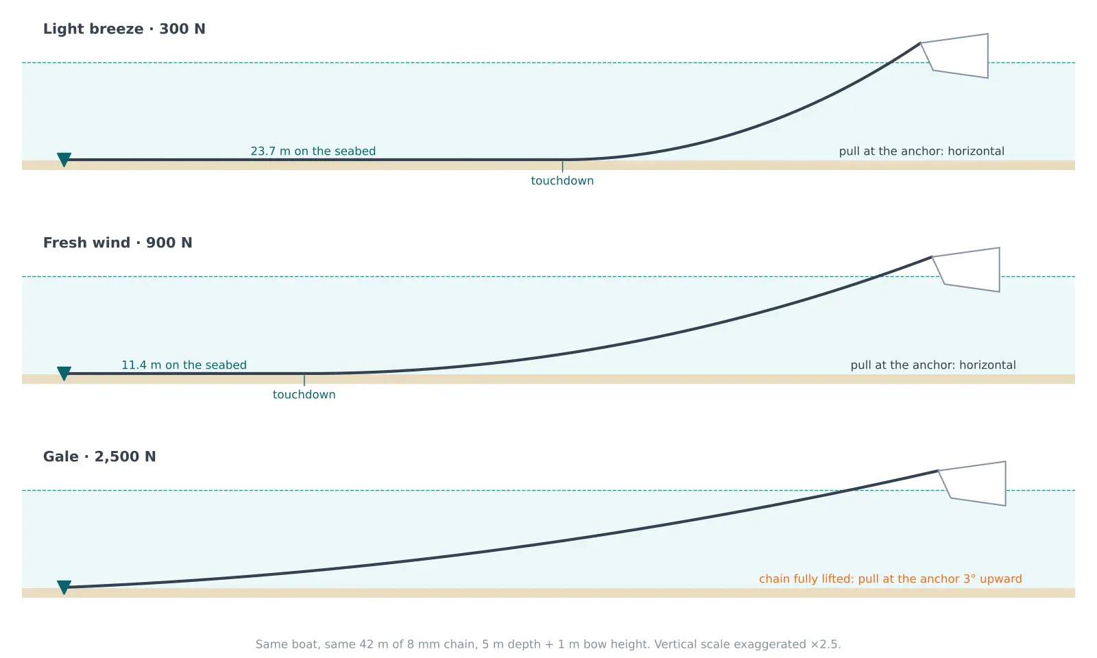
On a level seabed, a partially suspended rode leaves the bottom tangentially. In a simple static model the force at that touchdown point is horizontal. As the boat pulls harder, it lifts more links, and the touchdown point moves toward the anchor. Lifting those links stores gravitational energy and gives the boat room to move before tension rises sharply. The chain can return that energy as it settles. Its weight provides compliance through geometry.
First find the chain’s submerged weight per metre. Convert dry mass per metre to weight, then allow for the seawater displaced by the steel. For this calculation use conventional engineering approximations of 1,025 kg/m³ for seawater, 7,850 kg/m³ for steel and standard gravity rounded to 9.81 m/s². Treat galvanized chain as steel for this estimate.
w = dry mass per metre × 9.81 m/s² × (1 − seawater density / steel density)
For an 8 mm chain listed at 1.40 kg/m, that gives 1.40 × 9.81 × (1 − 1,025 / 7,850) ≈ 11.9 N/m. We’ll round to 12 N/m for the worked example. The dry mass comes from the William Hackett calibrated chain catalogue.
Now measure the vertical distance h from the seabed to the bow lead, and call the steady horizontal force H. Dividing H by w gives a length that measures how strongly the pull flattens the curve. The lifted length combines that length with the vertical rise. This static calculation assumes uniform chain, a level bottom, negligible chain stretch and drag, and a horizontal tangent at touchdown. Source: published mooring-chain analysis, flat-seabed case.
Lifted chain length = sqrt(h² + 2 × h × H / w)
In 5 m of water [16.4 ft], with the bow lead 1 m above the surface, h is 6 m [19.7 ft]. With a steady 900 N horizontal pull, the suspended length is sqrt(6² + 2 × 6 × 900 / 12) m ≈ 30.6 m. If you paid out 42 m, about 11.4 m remains on the seabed in this model. If you paid out only 30 m, the result tells you that the touchdown assumption has already failed. All the chain is up, and the pull at the anchor has an upward component.
You can turn the same calculation around. Put the entire deployed chain length L in place of the lifted length to find the horizontal force at which the last link just comes off the bottom. At that instant the model still has a horizontal tangent at the anchor.
Lift-off force = w × (L² − h²) / (2 × h)
For 30 m of chain at h = 6 m, lift-off is 12 × (30² − 6²) / (2 × 6) N = 864 N. For 42 m it is 1,728 N. That second figure is a geometry threshold. The anchor may drag before it, or hold well beyond it. It marks the onset of upward pull at the shank.
3. Scope and the angle at the anchor shank
Scope compares the rode you deploy with the full vertical distance from the anchor to the bow lead. Take the water depth at the anchor, correct for the depth sounder’s reference point and any expected rise in water level, then add the height of the loaded bow lead above the surface.
Scope = deployed rode length / vertical distance to the bow lead
A 30 m rode in the 6 m example gives 30 / 6 = 5, or 5:1. If the water rises by another metre, the same rode gives 30 / 7 ≈ 4.3:1.
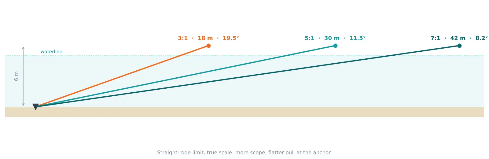
Picture the rode pulled almost straight. It forms the long side of a right triangle, and the vertical rise forms the side opposite the pull angle. The inverse sine, written asin on many calculators, converts their ratio into an angle. This gives the straight-rode limiting angle on a level bottom. A hanging chain can pull at a much smaller angle before it approaches that limit.
Straight-rode angle = asin(vertical distance / deployed rode length)
At 5:1, asin(6 / 30) ≈ 11.5°, with the calculator in degree mode. At 3:1 the limit is 19.5°, and at 7:1 it is 8.2°. In this example those choices require 18, 30 and 42 m of rode. Each pays out more room for the boat to swing as well as reducing the steepest pull angle. Allow for the hull extending beyond the bow, other boats swinging on different rodes, and hazards throughout the swing area. Source: Rocna’s scope and catenary guidance.
| Pull angle above the seabed | Holding capacity relative to horizontal pull |
|---|---|
| 0° | 100% by definition |
| 6° | 85% |
| 12° | 62% |
| 20° | 50% |
These percentages come from U.S. Navy salvage guidance for beach-gear anchor systems, section 8-3.4.4. They illustrate the scale of a possible loss. Your anchor’s response depends on its design, how deeply it is set, and the seabed. Applying those percentages to a yacht anchor’s advertised holding figure would require test data for that anchor and bottom.
4. Estimating the wind load on your boat
Wind force grows with the area the wind sees and with the square of the wind speed. Think of the boat’s silhouette viewed from upwind. Count the exposed hull, cabin, sprayhood, furled sails, mast and any tender carried on deck. Rough rectangles and triangles are enough for a first estimate. Use a bow-on view and repeat the estimate with the boat turned partly sideways if it yaws at anchor. Avoid counting the same area twice where shapes overlap.
The drag coefficient Cd accounts for how the shape and orientation interact with the airflow. Here A is projected area in square metres, v is wind speed relative to the boat in metres per second, and ρ is air density in kg/m³. The standard drag equation gives the force in newtons. Use 1.225 kg/m³ as the standard sea-level air density. Each knot is one nautical mile per hour, or approximately 0.5144 m/s by unit conversion. Source: NASA Glenn’s drag equation.
F = 0.5 × ρ × Cd × A × v²
Take a hypothetical 9 m [30 ft] sailboat. Assume 6 m² of projected area and Cd = 1.0 for the worked example. These are inputs for this example. Substitute your own area and use a drag coefficient appropriate to the shape and heading where data are available. At 30 knots, v is about 15.43 m/s, so the load is 0.5 × 1.225 × 1.0 × 6 × 15.43² ≈ 875 N.
| Wind speed | Wind speed in SI | Estimated wind force |
|---|---|---|
| 20 knots | 10.29 m/s | 389 N |
| 30 knots | 15.43 m/s | 875 N |
| 40 knots | 20.58 m/s | 1,556 N |
At 40 knots the example boat sees four times its 20-knot wind force. If the effective drag area doubles as it yaws, the estimated force doubles again at the same wind speed. Compare the 30-knot result with the earlier lift-off thresholds. Under this idealised, steady wind-only load, 30 m of 8 mm chain is just off the bottom. With 42 m out, some chain remains grounded even at the 40-knot wind-only estimate. Current adds its own load and can act from a different direction. Chop and yaw create transient peaks, so these figures are inputs for comparing arrangements and cannot establish a safe wind limit.
5. Shock loads, gusts and the snubber
A gust raises the wind force. It can also get the boat moving before the rode arrests it. When the remaining curve is shallow, further movement lifts relatively little extra chain. A nearly straight chain then gives the moving boat very little distance to slow down. Steel stretches under tension, but very little compared with nylon in this application.
Imagine two otherwise identical stops in which the rode must take up the same energy. The average extra force required to absorb that energy is the energy divided by the distance over which the rode absorbs it. The peak depends on how force builds during the stop.
Average extra stopping force = energy to absorb / stopping distance
Suppose a surge leaves 300 J for the rode to absorb. Over 0.10 m the average extra force is 300 J / 0.10 m = 3,000 N. Over 0.50 m it is 600 N. Those are chosen numbers to illustrate the physics. Real peak loads depend on the boat’s motion, the existing rode tension, and the rope’s wet load–elongation behaviour.
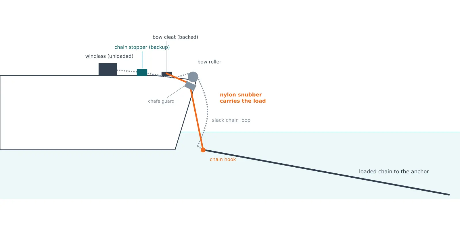
With all-chain rode, a properly sized nylon snubber provides stretch after the catenary has largely flattened. Lead it to a suitably backed cleat or strong point, protect it where it rubs, and attach it with a chain hook or a rolling hitch, then ease chain until the rope carries the load and a slack loop hangs behind the attachment. Secure a backup load path through a suitable chain stopper or strong point so a failed snubber cannot leave the windlass taking the shock. More working rope length generally gives more stretch at the same tension for the same construction and diameter. Choose a nylon line and use the rope maker’s load and elongation data and inspect the line where it passes through a fairlead. Sources: Mantus installation guidance and Practical Sailor snubber testing.
6. What changes from 6 mm to 8 mm to 10 mm?
These are published ranges (see also our calibrated anchor chains) across two suppliers’ hot-dip galvanized calibrated G40 products. The breaking forces include rounded conversions from catalogue kilogram-force figures where applicable. The last two columns use representative masses within those ranges and the equations above, for 42 m deployed and a 6 m bow-to-bottom rise.
| Diameter | Dry mass | Published breaking force | Dry mass of 42 m | Calculated lift-off force |
|---|---|---|---|---|
| 6 mm | 0.80 kg/m | 20–23.5 kN | 34 kg | 0.98 kN |
| 8 mm | 1.40–1.42 kg/m | 40–42.2 kN | 59 kg | 1.72 kN |
| 10 mm | 2.14–2.25 kg/m | 63–66.2 kN | 92 kg | 2.70 kN |
Source: Lofrans manufacturer specifications and William Hackett calibrated chain catalogue. For the calculations, representative masses are 0.80, 1.40 and 2.20 kg/m. The small difference between 1.72 kN here and the earlier 1.728 kN comes from using unrounded submerged weight in the table.
Why choose 8 mm over 6 mm? In this comparison, about 25 kg more steel in the bow buys roughly twice the published breaking force and about three-quarters more horizontal load before lift-off at equal length and depth. If 6 mm already meets the required service load and fits your gypsy, it may make sense on a boat sensitive to bow weight, especially if the saved weight lets you carry more usable scope. On a heavier, high-windage boat, the strength and extra submerged weight of 8 mm can both be worth having. Moving to 10 mm continues the trade-off and adds more weight for the windlass, bow and crew to handle.
G30, G40 and G70 identify strength classes within a supplier’s chain system. At the same diameter, a higher grade can buy more strength with little change in mass, so it provides little extra catenary by itself. William Hackett lists its calibrated 8 mm G30 and G40 at the same 1.40 kg/m, with breaking forces of 32 and 40 kN respectively. A marine G70 product can be useful where strength per kilogram matters. Confirm its coating, calibration and ratings for anchor service. Check gypsy fit and working load separately. Source: William Hackett calibrated chain catalogue.
Read the working load limit (WLL) and minimum breaking load (MBL) as separate specifications. A proof load is a manufacturing test load. For selection, obtain the supplier’s working or service rating for the exact chain and check it against a design load that accounts for the boat, exposure and dynamic loading. The wind-only calculation is a starting input. A large ratio between breaking load and steady wind force says little about a damaged link or an unaccounted-for shock. Match the gypsy to link pitch and dimensions as well as diameter — a windlass made for 6 mm chain will not take 8 mm, and the same diameter in a different pitch may jump the gypsy. The Lofrans catalogue, for example, shows 10 mm DIN and ISO variants with 28 mm and 30 mm pitch respectively.
7. All-chain versus chain and rope
All-chain rode tolerates bottom abrasion well and gives the windlass a consistent surface to grip. The weight helps keep the pull low while some chain is grounded. Once the curve flattens, the snubber supplies the working stretch. Check for chain piling up under the hawsepipe during retrieval.
With a mixed rode, chain near the anchor protects the lower end where it rubs along the bottom. Nylon farther up supplies elastic travel and makes it easier to carry reserve rode without loading the bow with steel. As the rope takes up tension, it can lift the chain clear. The uniform all-chain lift formula cannot predict that mixed shape because the two materials have different submerged weights and stretch. Use total deployed length for scope. Select enough chain for the abrasion and handling expected at your sites, check how the rope runs through the lead at low tide and through the swing, and match the splice and rope construction to the windlass if it will handle both.
8. The hidden cost of grounded chain: seagrass
Everything so far has treated the chain lying on the seabed as a good thing. It keeps the pull at the anchor horizontal and gives the boat a reserve of catenary. Now follow that same chain through a night at anchor. The wind shifts, the boat swings, and the grounded section pivots around the anchor like a windscreen wiper, dragging steel across whatever lies underneath.
You can estimate the area it sweeps with the numbers from Section 2. With 42 m deployed and a steady 900 N pull, about 11.4 m of chain lies on the bottom. If the boat swings through 180°, that grounded length sweeps a half-circle:
Swept area ≈ ½ × π × (grounded length)²
½ × π × 11.4² ≈ 204 m² — roughly the floor area of a large house — in a single wind shift. A full swing doubles it to about 408 m². In practice the grounded length grows and shrinks as the load changes, so the real footprint is a ragged ring rather than a neat half-disc, but the order of magnitude holds.
On sand this leaves a scar that the next storm erases. On Posidonia oceanica, the Mediterranean’s endemic seagrass, it does not. The meadows grow extremely slowly and store carbon in their root mat over centuries, which is why they are increasingly protected. Source: The Ecologist on Posidonia and anchoring.
There is also a purely selfish reason to avoid it: an anchor holds poorly in seagrass. The fluke lands on a dense mat of leaves and rhizomes and often cannot penetrate to the sediment that gives it holding power. It may appear set under light load, then skate across the mat when the wind rises.
How to avoid it
- Look before you drop. In clear water, Posidonia shows as dark green-brown patches; clean sand is pale. Many chart apps and local guides now mark seagrass areas.
- Aim for a pale sand patch large enough to contain your anchor and the swing of your grounded chain.
- Use a mooring buoy where one is provided; eco-moorings are being installed in several Greek islands for exactly this reason. Source: Greek Islands Sailing on anchoring rules and eco-moorings.
- Retrieve vertically: motor up to the anchor rather than dragging it out with the windlass.
The rules are tightening. France bans vessels over 24 m from anchoring in seagrass meadows, the Balearic Islands banned anchoring on seagrass outright in 2018, and in Greece anchoring on Posidonia is prohibited in high-protection zones, with rules increasingly set by local and protected-area authorities rather than a single national law. Check the local regulations wherever you cruise. Sources: The Ecologist, Greek Islands Sailing and SuperyachtNews on the 2026 Mediterranean anchoring regulations report.
9. Check the shackles, swivels and other connectors
Follow the load from the buried fluke to the hull. Check the shackle, swivel if fitted, chain, rope splice, hook, cleat and backing. Compare the maker’s working ratings on the same basis, including any reduction for side loading or the specific way the hardware is installed. Check the fit in the actual anchor slot and chain link. A connector that binds can put leverage on its pin or jaws when the boat swings.
Crosby’s engineering tables, for instance, reduce the in-line rating of specified screw-pin and bolt-type shackles under side load. Use the table for your model and follow its pin-securing instructions. For the anchor end of the rode we stock galvanized D-shackles to match galvanized chain, stainless D-shackles with an Allen-key pin that sit flush and can be moused with seizing wire, and tested bow shackles with a stated working load. Swivels need the articulation and installation specified by their maker so they can align under load. We stock a 316 stainless anchor swivel for two chain size ranges and an angled version that helps the anchor turn the right way up in the roller. Whichever you choose, check the rated load and permitted installation for that exact version. Source: Crosby application data.
10. Quick reference for sizing your ground tackle
Start with your loaded displacement and the anchor maker’s chart (or browse our anchors). Then use your deepest planned anchorage and chosen scope to work out the minimum deployable rode for that scenario. Multiply scope by the full seabed-to-bow rise. For example, 7:1 at a 6 m rise requires 7 × 6 m = 42 m. If the system is all-chain, the full 42 m is chain. For a mixed rode it is the combined length. Carry enough additional length for deeper water, changing conditions and the section needed to secure the rode aboard.
| Example boat length | Assumed loaded displacement | Example Rocna Original mass | G40 chain candidate to verify | Assumed max. rise | Minimum deployable rode at 7:1 |
|---|---|---|---|---|---|
| 5 m [16 ft] | 0.8 t | 4 kg | 6 mm | 4 m | 28 m |
| 8 m [26 ft] | 3 t | 9 kg | 6 mm | 5 m | 35 m |
| 10 m [33 ft] | 5 t | 12 kg | 8 mm | 6 m | 42 m |
| 12 m [39 ft] | 9 t | 15 kg | 8 mm | 8 m | 56 m |
| 15 m [49 ft] | 15 t | 25 kg | 10 mm | 10 m | 70 m |
Anchor masses are model-specific selections from the Rocna manufacturer chart, using its 16 m row for the 15 m example. Boat displacements and rises are scenario inputs. Chain diameters are candidates for checking against the actual service load, gypsy and locker, and the 7:1 minimum applies to these scenarios. Two boats of the same length can have very different windage and displacement. If your calculated scope cannot fit the swing area, consider a different anchoring spot.
11. FAQ
Can heavier chain make up for short scope? It can keep the pull flatter at a given modest load. Once the rode is nearly straight, the length you deployed and the height of the bow lead determine its angle.
Does 7:1 guarantee a horizontal pull? Only while the chain leaves the seabed horizontally near the anchor in the idealised case. At high tension the straight-rode limit on a level bottom is about 8.2°.
Should I size the anchor by boat length or displacement? Use both if the anchor maker’s chart asks for them, and use the boat’s loaded displacement. Check the maker’s guidance for multihulls, high windage and the seabeds you normally use.
Is a short nylon strop enough? It can take the load off the windlass, but its useful stretch may be small. Check how far the specific line elongates under load and give it enough working length and chafe protection.
Can I add a swivel to stop dragging? A swivel helps with twist during retrieval. Holding depends on the anchor’s set, the seabed and the loads applied to it, and adding a swivel gives you another fitting to size and inspect.
Is it OK to anchor on seagrass if I am careful? Avoid it. The anchor holds poorly in the leaf mat, the grounded chain sweeps a large area as you swing, and in many Mediterranean areas it is now prohibited. Choose pale sand or a mooring buoy.
How do I tell whether the anchor is set? After laying out the rode, increase reverse thrust progressively while monitoring a fixed shore transit or position trend. After the rode takes up, check that the boat settles into a stable position under load, then keep monitoring as the wind or current changes.
Need help choosing? Ask us. Tell Nafpaktos Marine your boat’s loaded displacement, bow lead height, usual anchoring depths and windlass model. If you have the existing chain’s markings or dimensions, send those too so we can help you check what fits.

Marine Technician – Nafpaktos Marine founder
Marine engine specialist working with fishing vessels, charter boats and just about anything that floats.